Created Sep 30, 2023 - Last updated: Sep 30, 2023
Ever wanted a super cheap antenna for VHF that you can smash about when out ‘doing’ SOTA? Well look no further. The print-o-matic flowerpot (tm)
Ask 10 hams any “What’s the best….” question and you’ll get 10 (or maybe more) answers.Especially when it comes to antennas.
I tend to operate mostly /P on SOTA and WOTA summits that are local to me. Local is the Lake District. It comes with a few ‘features’. It rains a lot and as I live by the coast it gets windy at ground level as well as up on the tops. So, for me, answering the ‘Best 2m antenna for SOTA and WOTA’ question is a no brainer. Its the flowerpot. Sometimes called a sleeve dipole. It has a few advantages:
- Its cheap – After all its just a bit of coax
- It doesn’t mind getting beaten up
- It performs pretty well, yes a yagi is going to be better but they can be annoying in wind.
- It is easy to make, and make again and again if it gets broken.
My first one was a gift from G4VFL. A bit of blue water pipe, a bit of wood stuffed inside with the coil formed round the wood and a piece of fibreglass to support the coax.
Mk2 is err highly developed. Well its just a 3D printed version which makes it easier to keep the coil in place and so it can be replicated easily and cheaply.
Dimensions
All you need to know is that they are all over the internet. John Bishop, VK2ZOI gave me the ones I needed to know. That is the coax is pared back about 460mm with just the inner ‘showing’ and a further length of about 450mm up to the coil. As always YMMV.
The G7KSE design
Essentially the same as John’s but instead of RG58 coax I’ve opted for RG174 this time and I’ll see how it goes. The coil is formed on the base which has a 25mm ID hole in it to sit on my adapted setup. Everything I have mates to 25mm parts just so you’re aware. The design looks a bit like this
I use a browser based bit of software called Onshape. All my designs are public and things like STL’s go onto the Printables. You can get all the details from there.
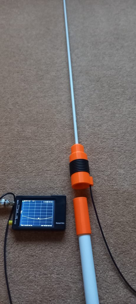
So here is a quick picture of it finished with a flat-ish SWR curve around 1.6:1 in free space. A bit more when its on the floor as you can see here.
Parts needed
- RG174 – about 3m
- 1m of 6mm fibreglass. EC Fibreglass will help you out
- A BNC connector for RG174 – I use crimped ones with a bit of heat shrink for strain relief.
- A 3D printed base
- A 3D printed end cap
Assembly
- Prepare the coax – Mark the length of inner needed and carefully cut the outer and braid. Remove them without cutting the inner.
- Put a mark on the coax where the coil needs to start. A sharpie is enough.
- Push the inner section through the top hole and feed it through the top hole. You shouldn’t need 3 hands for this 🙂
- Make sure the marked bit has gone just inside the hole.
- Wind the coil tightly and push the remaining coax through the bottom hole.
- Give everything a ‘tighten’ to make sure the coil is well seated
- Dab a bit of epoxy on the end of the fibreglass tube. A small ring round the leading edge is perfect.As you push it in give it a twist to cover the surfaces with the glue.
- Do the same at the other end and twist the end cap on.
- Let it all cure
- Fit the connector
- Enjoy
All being well then it will work first time.If you want to optimise / fiddle about then test fit everything up to step 6 then once you are happy carry on and complete the job.